 EN
EN
 CZ
CZ


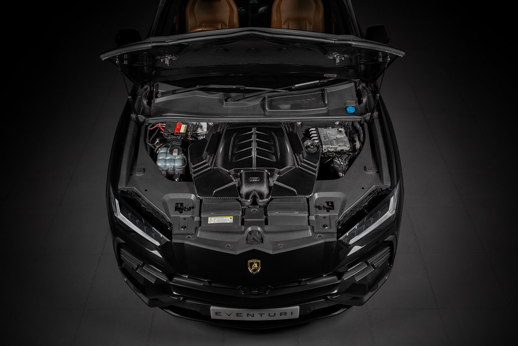
Eventuri carbon intake for Porsche Cayenne 4.0T 2022+
Eventuri carbon intake for Lamborghini Urus, Audi RSQ8, Porsche Cayenne, Bentley Bentayga and other models with 4.0TFSI V8 EA825 engines. The intake has redesigned carbon airbox lid, two conical filters, larger collector and turbo inlets with dimpled inner surface.Full description
Eventuri carbon intake for Porsche Cayenne 4.0T
(Lamborghini Urus with the same engine shown on image)
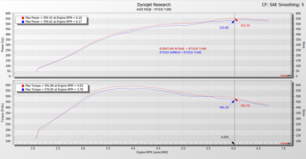
Performance gain stock ECU: + 14-20 k | + 23-28 Nm
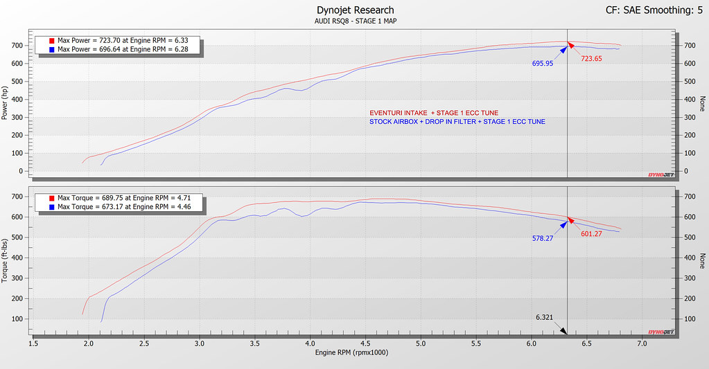
Performance gain Stage 1 ECU: + 25-28 k | + 27-31 Nm
Our 4.0TFSI V8 EA825 intake is a ground-up redesign and optimisation of the entire air inlet track. Every component including the lid has been developed to allow the V8 twin turbos to pull in air with less drag resulting in industry leading performance gains. The stock airbox lid itself creates a restriction on the size of the flow collector which feeds the inlets from the filters. So we increased the height of the central section of the lid to allow for a larger flow collector and larger cone filters to be used. This removes the inherent restriction and sets our intake apart from the rest of the field who by utilising the stock lid must also use a restricted collector and filtration media.
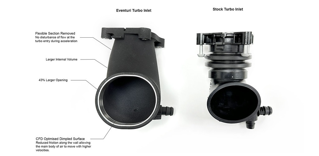
The turbo inlets are up to 43% larger in cross sectional area than stock and are designed with an advanced dimpled inner surface to reduce frictional losses between the flow and the wall boundary. By allowing a “cushion” of air at the wall surface, airflow is able to move through the inlets at higher flow rates with reduced pressure loss. This allows the turbos to draw air with less resistance and therefore reduce the wastegate duty cycle resulting in higher overall performance.
The Eventuri 4.0TFSI V8 intake system consists of a number of components engineered to perform a specific purpose and fabricated to the highest of standards. We use 100% pre-preg carbon fiber with no fibreglass which means we can achieve a smooth internal surface to maintain smoother airflow. Here are the details for each component and the design ethos behind them:
Each intake system consists of:
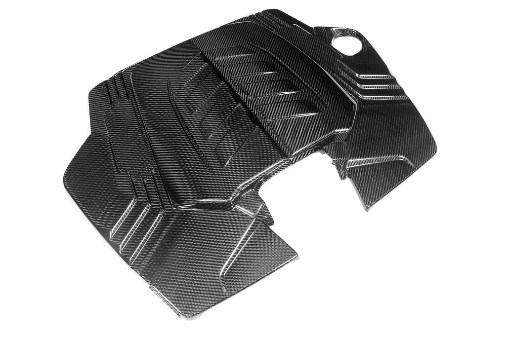
- Enlarged Carbon Fiber AIrbox Lid
- Carbon Fiber Flow Collector
- 2 Thermoplastic Turbo Inlets with Dimpled Inner Surface
- 2 x Bespoke High Flow Dry Cone Filters
- Custom Flexible Hoses
- CNC Machined Breather Ports and Reinforcement Rings
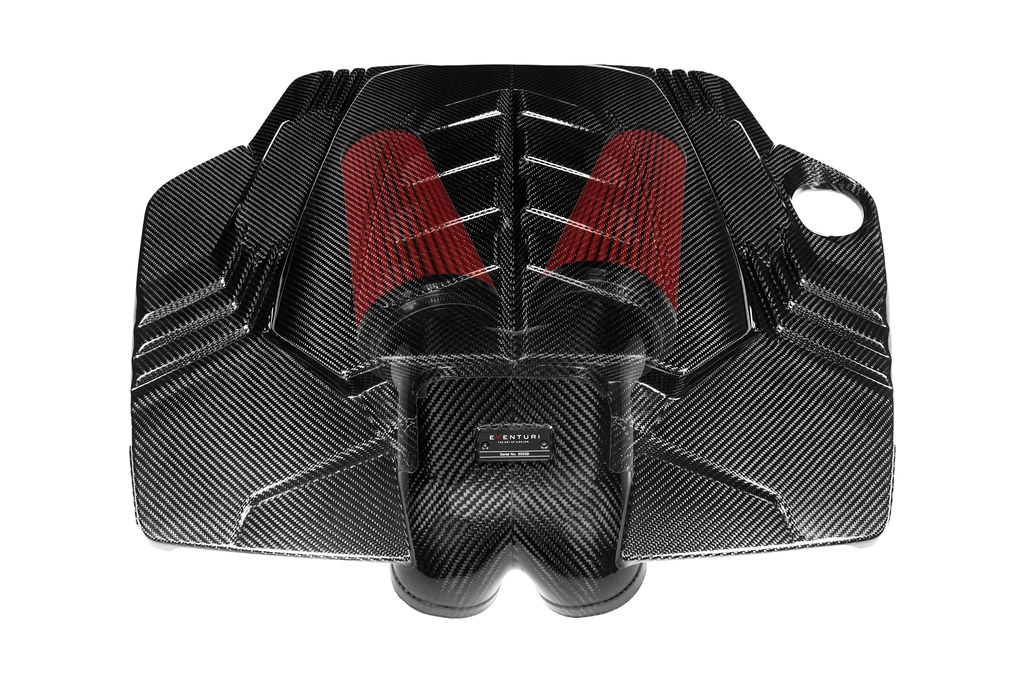
ENLARGED AIRBOX LID:
The first constraint we had to overcome in order to dramatically increase the overall volume of the intake was the airbox lid. The stock lid leaves a shallow opening for the flow collector and also restricts the filtration medium being used. By creating a raised portion in the middle of the lid we are able to create more space for a larger flow collector and also for larger filters. The lid is made from prepreg carbon fibre and uses the same mounting points as the stock lid.
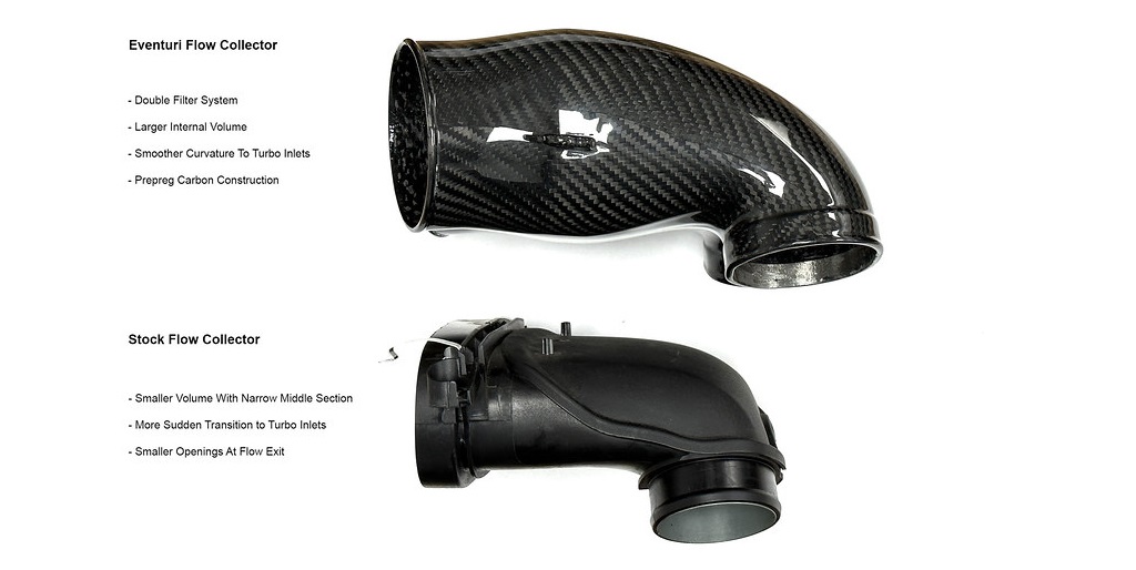
CARBON FLOW COLLECTOR AND FILTERS:
Directing the airflow from the filters to the turbo inlets is the flow collector. The stock one is constricted in size due to eth stock kid but having removed that restriction, we were able to dramatically increase the volume of our version. In addition, this also gave us the freedom to replace the stock filter with higher flowing cone filters which also have a larger total surface area.
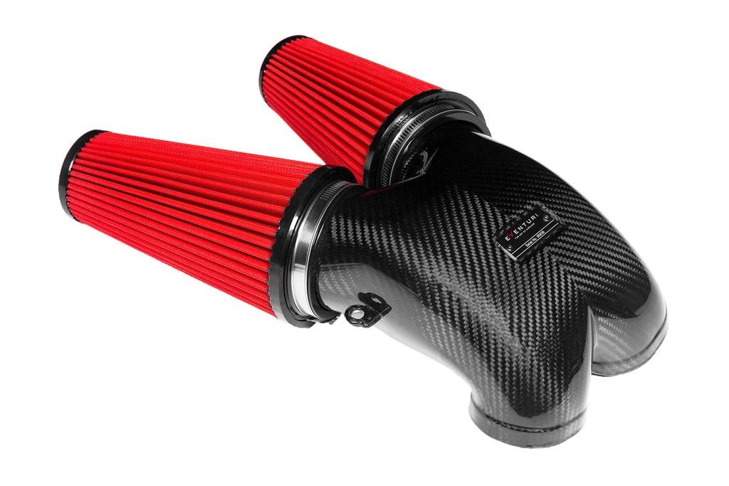
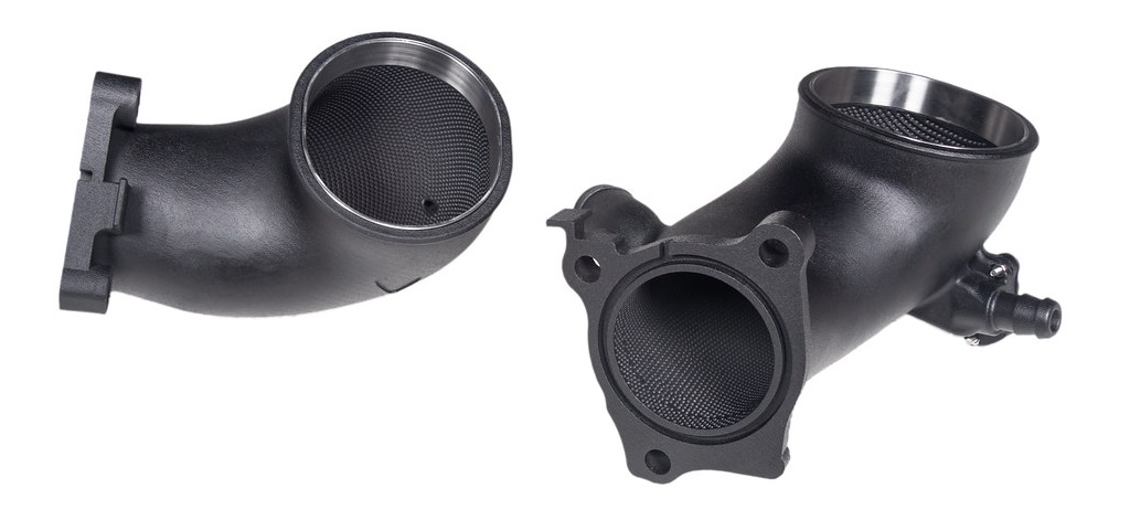
TURBO INLETS:
The biggest restriction in the stock system are the turbo inlets. The stock inlets not only are small in size but they also have 2 flexible sections. The flexible section immediately in front of the turbo creates turbulence as the engine moves under acceleration. To combat this, the stock inlets also have flow guides at the exit of the inlets but these also create a restriction. We removed the first flexible section which also meant that we could increase the internal volume. By increasing the inlet sizes, the turbos are able to pull in air with less restriction hence allowing for a quicker spool. In the following photos you can see the differences in the sizes.
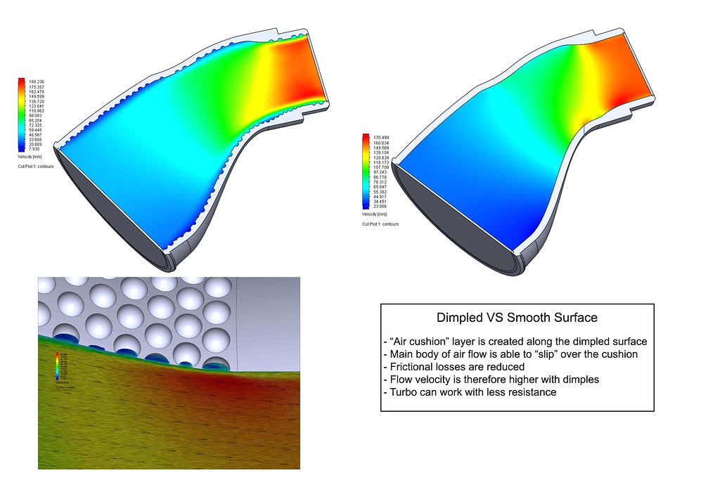
We could have finalised the designs here however, we wanted to push the boundaries further and introduce a novel dimpled pattern to the inside surfaces. In theory, small dimples can increase the flow rate by reducing the frictional pressure losses through a tube.
A lot of R&D went into simulating different sizes and shapes until we settled on an optimised version which demonstrated a higher flow rate through the inlets in comparison with a smooth surface. Applying such an intricate was only possible due to the advanced manufacturing technique we employed to make the inlets, where traditional methods would not have given the accuracy required. The dimples create an "air cushion" affect over the surface of the inlet which then allows the main body of air to "slip" with less friction through the body into the turbo. This results in a more even velocity profile in a dimpled tube with the net affect being a higher velocity for the same boundary conditions. Here are the CFD simulations showing the re-circulations in the dimples and the higher velocity in the dimpled tube.
Parameters and specifications

Our company Escape6 is on the market since year 2000. Our open and positive approach to vehicle modifications, besides many years of experience, stems from the enthusiasm of our entire team. Each of us is a true car enthusiast, and so we can identify with your idea of car modifications, whether it's a Show&Shine competitor, circuit racer, or offroad driver. We actively visit automobile exhibitions around the world, as well as domestic tuning exhibitions, events and events where you can meet our own modified cars.
We are looking forward to seeing you in our showroom in Prague Čestlice, which is filled with the best of today's world tuning parts and accessories. Whether you are only looking for small accessories or car care products, or if you want your car to be completely "tuned out", you are in the right place with us! And do not forget to follow us on social networks where you can learn something behind the scenes of our company.
We are fast
We have own warehouse with most of products in stock.
(c) 2019 Escape6 s.r.o., Cestlice 272, 251 01 Cestlice
Tuning shop, shop and showroom in Prague
Phone: +420 222 519 645 | e-mail: info@escape6.cz